Electronic connectors, also known as plugs, are widely used in a variety of electrical circuits, play a role in connecting or disconnecting the circuit. The first is the responsibility of the manufacturer to improve the reliability of electronic connectors. However, due to the wide variety of electronic connectors, a wide range of applications, therefore, the correct choice of electronic connectors is to improve the reliability of electronic connectors is an important aspect. Only through the joint efforts of both manufacturers and users, in order to maximize the electronic connectors should function.
Electronic connectors have different classification methods. In accordance with the frequency points, there are high-frequency electronic connectors and low-frequency electronic connectors; in accordance with the shape of rounded electronic connectors, rectangular electronic connectors; in accordance with the use of points, with printed circuit board electronic connectors, electronic connectors cabinets, Audio equipment with electronic connectors, power electronic connectors, special-purpose electronic connectors, and so on. The following describes the low-frequency electronic connectors (frequencies below 3MHZ) selection method.
ELECTRICAL PARAMETERS REQUIREMENTS
An electronic connector is an electromechanical component that connects electrical circuitry. Therefore, the electronic connector itself is the electrical parameters of the first choice of electronic connectors to consider.
Rated voltage
Rated voltage, also known as operating voltage, which depends mainly on the use of insulation materials used in the machine, the distance between the size of the contact. Some components or devices may fail to perform their intended function at voltages below their rated voltage. The nominal voltage of an electronic connector is in fact understood as the maximum operating voltage recommended by the manufacturer. In principle, the electronic connector in the rated voltage below normal work. I tend to be based on the electronic connector pressure (electric strength) indicators, in accordance with the use of the environment, safety requirements to a reasonable selection of rated voltage. In other words, the same pressure indicators, according to different use of the environment and safety requirements, can be used to different maximum operating voltage. This is also more in line with the objective use.
Rated current
Rated current, also known as operating current. As with the rated voltage, below the rated current, electronic connectors are generally able to work properly. In the design of electronic connectors, the thermal design of electronic connectors meets the rated current requirements because contact pairs will generate heat due to the presence of conductor resistance and contact resistance when current flows through the contact pair. When the heat exceeds a certain limit, it will damage the electronic connector insulation and contact with the surface coating softening, resulting in failure. Therefore, to limit the rated current, in fact, to limit the temperature inside the electronic connector does not exceed the design of the specified value. In the choice of the problem to be aware of: multi-core electronic connectors, the rated current must be derated use. Such as φ3.5mm contact pairs, the general provisions of its rated current of 50A, but in the 5-core to derate the use of 33%, which is the core of the rated current is only 38A, the core of the number of The more, the greater the magnitude of the derating
Contact resistance
The contact resistance is the resistance of the two contact conductors at the contact portion. In the selection should pay attention to two issues, first, the electronic connector contact resistance index is in fact contact with the resistance, which includes contact resistance and contact resistance of the conductor. Usually the conductor resistance is small, so the contact resistance in many technical specifications is called the contact resistance. Second, in the connection of small-signal circuit, pay attention to given contact resistance index is under what conditions, because the contact surface will be attached to the oxide layer, oil or other contaminants, the two contact surface will have a layer resistance . In the film thickness increases, the resistance increases rapidly, the film becomes a poor conductor. However, mechanical breakdown of the film occurs at high contact pressures, or electrical breakdown occurs at high voltages and currents. For some small size of the electronic connector design contact pressure is very small, the use of only the mA and mV level, the film resistance is not easy to breakdown, may affect the transmission of electrical signals. In GB5095 "electrical equipment in the electrical components of the basic test procedures and measurement methods," one of the contact resistance test method "contact resistance - millivolt method" provides that in order to prevent the insulation film on the contact breakdown, the test circuit open-circuit electromotive force Of the DC or AC peak should not be greater than 20mV, DC or AC test current should not be greater than 100mA. In fact, this is a low-level test method of contact resistance, therefore, there is a requirement for the selection, due to selection by the low-level contact resistance indicators of electronic connectors.
Shielding
In modern electrical and electronic equipment, the density of components and their increasing function between the relevant electromagnetic interference has placed a strict limit. So the electronic connector is often enclosed with a metal shell to prevent internal electromagnetic radiation or electromagnetic interference by the outside world. At low frequencies, only the magnetic material to the magnetic field from the obvious shielding effect. At this point, the electrical continuity of the metal shell has a certain requirement, that is, shell contact resistance.
Safety parameters
Insulation resistance
The insulation resistance refers to a resistance value which is exhibited by applying a voltage to the insulating portion of the electronic connector, thereby causing a leakage current in the surface or on the surface of the insulating portion. It is mainly affected by insulation materials, temperature, humidity, fouling and other factors. Insulation resistance values provided on electronic connector samples are generally values of the standard atmospheric conditions, in some environmental conditions, the insulation resistance value will be an unnecessary degree of decline. Also pay attention to the insulation resistance of the test voltage value. A different voltage is applied depending on the insulation resistance (MΩ) = the voltage (V) / leakage current (μA) applied to the insulator. In the electronic connector test, the applied voltage is generally 10V, 100V, 500V third gear.
Pressure resistance
The withstand voltage is the critical voltage between the mutually insulated portions of the contact pair or between the insulating portion and the ground, which is higher than the rated voltage for a specified period of time without causing a breakdown phenomenon. It is mainly affected by contact spacing and creepage distances and geometries, insulator materials, and environmental temperature and humidity, atmospheric pressure.

 Company Profile
 Company Culture
 Honor
Honor Corporate image
 Video Center
 Connector series
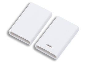 Structural parts series
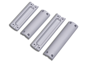 Machining series
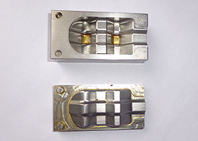 Mold Center
 Product information
 Corporate videos
 Company News
 Industry News
 Contact
 Feedback
 Recruitment